

A machine attachment can retain a clean-looking head while moisture trapped beneath its washer attacks the bearing surface or engaged threads. Another joint may appear heavily rusted yet require a different disposition because the damage location differs. I evaluate bolts through the exposed assembly, retained load path, and inspection capability. This article addresses material pairing, localized attack, coating damage, preload change, and evidence for continued use.
The connection begins with elastic bolt tension and compression through the bearing surfaces and clamped members. Corrosion can affect every part of that force path. It can remove material from a stressed section, alter the fit of engaged threads, damage bearing support, or change interface friction. I therefore assess the assembled system rather than interpreting the visible condition of the head as a complete description of the joint.
Electrochemical corrosion requires conditions that support the relevant reaction. Material identity, moisture, contaminants, electrical contact, and local exposure all matter. Dissimilar materials can create a galvanic interaction when the necessary conductive path and electrolyte are present. The actual geometry and exposed areas influence the response. A general material ranking cannot by itself establish compatibility for a buried thread, a coated washer, or a painted housing.
Local exposure can differ from the surrounding atmosphere. A washer edge, overlapped plate, or recessed bolt head can retain liquid and create a sheltered region with different oxygen access. Contaminants may concentrate as wet surfaces dry. A joint that drains freely can therefore behave differently from an otherwise similar connection that traps moisture. I map these locations before selecting an exposure test or inspection method.
Mechanical movement changes the surface condition as well. Sliding contact can wear a coating, expose the base material, and generate debris. Repeated motion and localized corrosion can then act together at a loaded interface. Tightening and removal also disturb protective surfaces. The finished assembly must be examined after representative handling and duty rather than only as an untouched coated specimen.
No technical standards or verified specification appendix were supplied. Exposure conditions, coating requirements, material limits, inspection intervals, and residual-capacity boundaries must be verified against current reports and approved engineering assessment before specification.
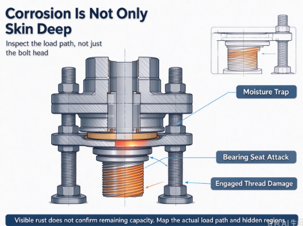
I identify each material and surface that can participate in the environmental and mechanical system. The coating on a bolt does not describe the finish on its Nut, washer, or supporting member. Contact between those surfaces can change during installation, and damage can develop where inspection is least accessible.
| Component | Material Spec | Function | Failure Risk if Compromised |
|---|---|---|---|
| Bolt body and threaded section | Verify finished alloy, heat treatment, stressed geometry, and environmental compatibility. | Carries tension and any approved bearing or shear demand. | Section loss, pit-assisted cracking, or environmental damage. |
| Protective coating and topcoat | Verify process identity, coverage, thickness evidence, adhesion, and service compatibility. | Controls exposure and influences assembly friction. | Localized attack, damaged fit, or altered preload. |
| Nut or tapped supporting member | Verify material pairing, usable thread condition, and surrounding section. | Reacts fastener tension through the engaged flanks. | Hidden corrosion, stripPing, or loss of thread support. |
| Washer and bearing seat | Verify material, finish, hardness, contact geometry, and drainage condition. | Distributes pressure and forms a potential sheltered interface. | Underside attack, indentation, or compression loss. |
| Clamped members and interface finish | Verify material pairing, surface treatment, contact condition, and stiffness. | Transfers load and defines moisture retention paths. | Fretting, crevice attack, separation, or distortion. |
| Sealing or isolation features | Verify composition, mechanical response, compatibility, and installation geometry where present. | Controls environmental access or electrical contact as designed. | Trapped moisture, degraded isolation, or added settlement. |
Verify all parameters against current test reports and applicable standards before use in specifications.
An isolation feature is not automatically beneficial. A compliant layer can reduce metal contact while also changing bearing support or creep behavior. A sealing feature can limit entry yet retain liquid if installed incorrectly or damaged. I qualify its environmental role and mechanical consequences together, including any effect on the torque-to-preload relationship.
Inspection access is another practical component of the design. If the critical section is buried inside a housing, an external photograph cannot establish its condition. The specification must identify whether the accepted inspection requires disassembly, a qualified examination method, or replacement under an approved policy.
I choose environmental testing from the service question, not from the availability of a generic exposure cabinet. The approved program must identify contaminants, wetting, drying, temperature, contact geometry, and mechanical loading where relevant. No universal conversion from a laboratory exposure duration to field life is established here.
| Parameter | Standard | Test Method | Acceptable Range | Implication if Out of Range |
|---|---|---|---|---|
| Coating condition after assembly and duty | Not supplied; verify the approved method. | Inspect representative contact locations after tightening, handling, and service simulation. | Verify the approved coverage and damage criteria. | Untested exposed regions control the service response. |
| Localized corrosion and section condition | Not supplied; verify the approved method. | Examine accessible and hidden regions using a qualified procedure. | Verify current residual-capacity and damage assessment limits. | Appearance fails to represent the controlling section. |
| Retained preload and interface movement | Not supplied; verify the approved method. | Measure joint force and movement before and after representative exposure. | Verify the required assembled load path. | Connection slips, separates, or redistributes load. |
| Usable thread condition | Not supplied; verify the approved method. | Inspect complete engaged flanks and assess capacity with the actual mating material. | Verify drawing and current structural evidence. | Hidden damage reduces engagement capacity. |
| Assembly and removal friction | Not supplied; verify the approved method. | Record the approved assembly response and separately characterize removal behavior. | Verify each process against its own acceptance purpose. | High removal resistance is mistaken for adequate preload. |
| Delayed material response | Not supplied; verify the approved method. | Assess finished processing history and approved sustained-load evidence. | Verify the actual material and process qualification. | Delayed cracking remains outside the acceptance record. |
Verify all parameters against current test reports and applicable standards before use in specifications.
After exposure, I preserve the specimen condition before cleaning. Deposits, contact marks, and attack distribution can identify moisture paths and movement. Cleaning may be necessary for measurement, but its method must be documented because it can remove evidence or alter the surface being evaluated.
Inspection uncertainty is important near a residual-capacity boundary. A small localized pit in a critical stressed region may require a different assessment from broad shallow discoloration. The method must resolve the feature that controls the decision; a coarse overall corrosion score cannot replace that measurement.
Protection starts with the actual environmental pathway. I identify where moisture enters, where it remains, and which materials are connected electrically and mechanically. Drainage, shielding, sealing, and isolation can influence exposure, but each must be assessed in its installed condition. An isolated loose fastener in a test chamber does not reproduce every sheltered region of a clamped joint.
Material pairing requires more than selecting a corrosion-resistant bolt. The nut, washer, housing, and coating can create a different electrochemical system from the fastener alone. Geometry matters because the extent of exposed surfaces and local electrolyte access can affect reaction distribution. I evaluate the assembled pairing and the possibility that damage occurs primarily in the supporting member rather than the bolt. Protecting the fastener while weakening its support is not an acceptable joint outcome.
Coating coverage must be reviewed after assembly. Rotation beneath a head or nut, contact at thread flanks, and sliding at the interface can disturb protective layers. The accepted process should identify whether those disturbed locations remain covered by the validated protection mechanism. I compare untouched specimens with assembled and duty-conditioned specimens so that the test does not approve a surface state that production installation cannot preserve.
The torque-to-preload relationship remains a separate acceptance dimension. Finish, lubricant, and surface aging influence rotational resistance. A corroded or contaminated assembly can require more torque to rotate while retaining inadequate compression. I do not use removal resistance as a substitute for preload measurement. Dry, lubricated, newly coated, and previously operated states require their own evidence when the installation or maintenance procedure relies on torque control.
Localized corrosion can affect both capacity and seating. Attack beneath a washer can reduce bearing support or change the effective compressed stack. Corrosion products can also influence contact and apparent tightness. I inspect the load-bearing surface and measure the retained joint state rather than judging solely by whether the head has moved. The mechanical consequence must be established for the location and geometry of the damage.
Effective thread engagement must be assessed in the exposed condition. Complete flank support can be reduced by damaged entry threads, corrosion within the engaged region, or debris that prevents full installation. Nominal hole depth and external bolt appearance do not establish usable capacity. I compare internal stripping, external-thread damage, bolt rupture, and surrounding-member failure using verified materials and the remaining geometry. Any destructive verification must preserve the actual exposure history.
Impact and fatigue can accelerate the consequences of surface damage. A slipping track or blade connection can wear its finish and create local bearing impact. Pits or damaged thread roots can then serve as stress concentrators under the resulting cyclic load. I examine load direction, grip, shear-plane location, and contact motion after environmental conditioning. A corrosion test and a separate new-part fatigue test cannot automatically establish the behavior of the exposed assembly.
Fretting and corrosion must also be distinguished during investigation. Repeated small movement can produce debris and surface damage that resembles environmental attack. Moisture may then contribute to a combined mechanism. I preserve the contact pattern and relate it to measured movement before selecting a corrective action. Changing coating alone cannot correct an interface that continues to slip outside its approved condition.
Hydrogen-related delayed damage needs its own evidence. Susceptible finished material, an available source, and sustained tension can combine during manufacturing or service. Cleaning and electroplating history must therefore remain traceable, together with finished hardness, applicable relief records, and approved sustained-load verification. A passing appearance or corrosion result does not establish that this mechanism is controlled. Manufacturing relief evidence also does not automatically qualify later environmental exposure.
Service inspection protects the accepted boundary only if it can detect the relevant deterioration. I identify the critical locations and the physical features that trigger further assessment, repair, or replacement. The interval and reject criteria must come from current evidence for the duty and exposure, not an arbitrary calendar period. Where hidden regions cannot be assessed reliably, the specification must define an approved alternative disposition.
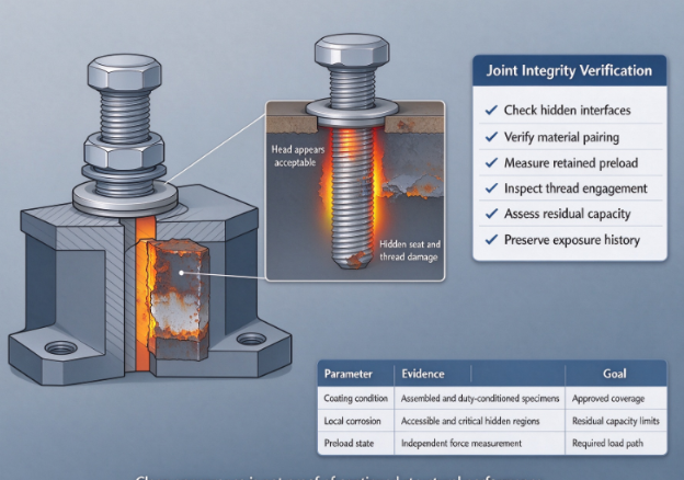
I investigate corrosion-related failures through location, load path, and exposure history. The visible amount of rust does not establish the remaining capacity or the cause of fracture. Mechanical records and preserved surfaces are needed to distinguish the following mechanisms.
Hidden bearing-seat attack occurs when moisture remains beneath a washer and damages the surface reacting clamp force. The consequence can be reduced support and preload change despite an intact-looking head. Prevention requires service-relevant assembled exposure testing and inspection of the actual bearing region.
Galvanic damage to the supporting member occurs when the installed material pairing and electrolyte condition promote attack of one component. The consequence may lie in the housing or washer rather than the fastener. Prevention requires evaluation of the complete pairing, local exposure, and any isolation feature.
Corrosion-assisted thread capacity loss occurs when attack reduces usable flank support or damages the surrounding tapped section. The consequence is stripping or unstable assembly resistance. Prevention requires qualified inspection of the engaged region and a residual-capacity assessment based on remaining geometry.
Fretting-related coating removal occurs when repeated interface motion wears the protective layer. The consequence is a changed environmental and fatigue condition. Prevention requires correction of the slip mechanism and validation of the coating in the duty-conditioned assembly.
Seizure mistaken for retained preload occurs when corrosion, deposits, or surface transfer increase removal resistance. The consequence is continued service based on an invalid mechanical inference. Prevention requires a method that assesses compression or the approved joint condition independently of removal torque.
Delayed environmental cracking occurs when a susceptible stressed material encounters conditions supporting environmentally assisted damage. The consequence can be fracture without the gross section loss expected from ordinary rusting. Prevention requires material and exposure assessment, preserved failure evidence, and an approved qualification addressing the actual mechanism.
I separate environmental protection, mechanical integrity, and inspection capability in the specification. Each requirement must define the installed configuration and the evidence supporting continued use. Numerical criteria remain subject to current reports and approved engineering review.
Structural: identify critical stressed sections, bearing surfaces, effective engagement, surrounding support, and residual-capacity requirements.
Structural: verify retained compression, permitted movement, and fatigue response after representative environmental conditioning.
Drive specifications: define qualified finishes, lubricants, mating combinations, assembly states, and the torque-to-preload evidence supporting installation.
Drive specifications: distinguish removal assessment from installation acceptance and define handling of seized or damaged components.
Environmental: identify material pairing, moisture paths, contaminants, sheltered regions, drainage, coating damage, and service exposure history.
Environmental: qualify sealing or isolation features for both environmental function and mechanical settlement.
Safety standards: confirm project-required requirements through approval; no standard designation or certification is supplied here.
Verification: define inspection access, cleaning procedure, measurement capability, evidence preservation, and approved disposition for hidden damage.
The specification should state what a passing exposure test actually covers. It must identify whether specimens were assembled, mechanically loaded, previously tightened, or intentionally damaged in a representative manner. Results from pristine coupons must not silently acquire the scope of a service-conditioned connection.
I also define the information needed after a field failure. Exposure location, cleaning history, operating loads, removal method, and component identities should be retained. Without those records, a replacement may repeat the original environmental mechanism or introduce a different unqualified material pairing.
Ningbo yi teng construction machinery CO,LTD is described in the supplied information as producing fasteners and machinery components for international markets. The bolts product page should identify verified finished configurations without presenting a coating description as proof of every service environment.
I evaluate whether engineering personnel can trace material and surface-processing history, assess mating compatibility, and explain the scope of environmental tests. Reports should distinguish coupon performance from assembled-joint behavior. Finished-condition inspection and retained mechanical evidence need a common component identity.
Failure-analysis capability must include hidden interfaces, mating parts, and exposure history rather than only photographs of the bolt head. The organization should identify where its evidence ends and where an application-specific assessment is required. No current certification is confirmed by the supplied technical-standards field; verify any required certification before specification.
Yes, sheltered bearing surfaces and engaged threads can experience conditions different from the visible head.
I map moisture paths and identify the critical inspection locations. External appearance cannot establish hidden capacity. The approved procedure must define how inaccessible regions are assessed or dispositioned.
No, compatibility depends on the complete material pairing and exposure condition.
The supporting member, washer, coating, and electrolyte path influence the assembled response. I examine where damage is expected to occur. Fastener resistance alone does not establish joint integrity.
No, corrosion and deposits can increase removal resistance independently of retained compression.
I distinguish the force needed to rotate a component from the force stored in the joint. A qualified measurement or approved physical assessment is required. Removal behavior may support diagnosis but cannot replace that evidence.
Only when a validated relationship exists for the actual environment and configuration.
Laboratory exposure can differ in wetting, drying, contaminants, loading, and contact geometry. I state the scope of the test rather than infer a universal life. Current reports must justify any service interpretation.
Preserve and document the original condition before any controlled cleaning.
Deposits and attack distribution can identify the exposure pathway. Cleaning can remove evidence or alter dimensions. Its method and purpose must remain part of the examination record.
Share your project parameters for a technical review.
担当者: ウーさん
電話:0086-13958324455
カスタマーサービス: +86-0574 88065928
電子メール: Sales@zjbzj.com
ファックス: +0086-0574 88065656

公式ウェブサイト
Copyright @ Ningbo yi teng Construction Machines CO,LTD主にブレードボルトシリーズ、六角ボルト、バケット歯に従事しています。お問い合わせ大歓迎です!
サイトマップこの Web サイトでは、お客様に最高のエクスペリエンスを提供するために Cookie を使用しています。
 English
 Español
 Portugues
 Pусский
 Français
 Deutsch
 한국어
 العربية
 हिन्दी



 ワッツアップ
 電話
コメント
(0)